This content is translated with AI. Please refer to the original Traditional Chinese version (zh-TW) for accuracy.
In the previous article, we built a SoC on PynqZ2 and were able to control it using the AXI Lite interface. However, using AXI in reality is relatively luxurious; simpler implementations typically use simpler APB or AHB buses. In this article, we will explain how to implement and connect an AHB IP and allow the PS side to access it.
Packing AHB IP
Implementing a Readable and Writable AHB Module
The module we demonstrate is a simple AHB without any address. Any write will be stored in the register, and reading will return the bit-inverted result. In this era, this kind of module can just be written with the help of AI. Below is the prompt and its reply:
Help me implement an AhbCli module, that we can write a 32-bit value and read the bit inversion of it.
module AhbCli #(
    parameter ADDR_WIDTH = 32
)(
    input  logic                  clk,
    input  logic                  rst,

    // AHB-Lite slave interface
    input  logic                  HSEL,
    input  logic [ADDR_WIDTH-1:0] HADDR,
    input  logic                  HWRITE,
    input  logic [1:0]            HTRANS,
    input  logic [2:0]            HSIZE,
    input  logic [31:0]           HWDATA,

    output logic [31:0]           HRDATA,
    output logic                  HREADYOUT,
    output logic                  HRESP
);

// -------------------------
// Internal register
// -------------------------
logic [31:0] reg_data;

// AHB valid transaction
logic trans_valid;
assign trans_valid = HSEL && HTRANS[1]; // NONSEQ or SEQ

// -------------------------
// Write logic
// -------------------------
always_ff @(posedge clk or negedge rst) begin
    if (!rst) begin
        reg_data <= 32'h0;
    end else if (trans_valid && HWRITE) begin
        reg_data <= HWDATA;
    end
end

// -------------------------
// Read logic
// -------------------------
always_comb begin
    if (trans_valid && !HWRITE) begin
        HRDATA = ~reg_data;
    end else begin
        HRDATA = 32'h0;
    end
end

// -------------------------
// AHB response
// -------------------------
assign HREADYOUT = 1'b1; // always ready
assign HRESP     = 1'b0; // OKAY

endmodule
Our goal is to pack the above IP into a block that can be placed in a block design and connected to the SoC.
Creating AHB IP
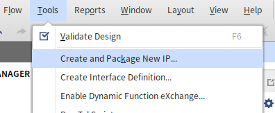
First, we need to open Vivado's Create and Package New IP menu.
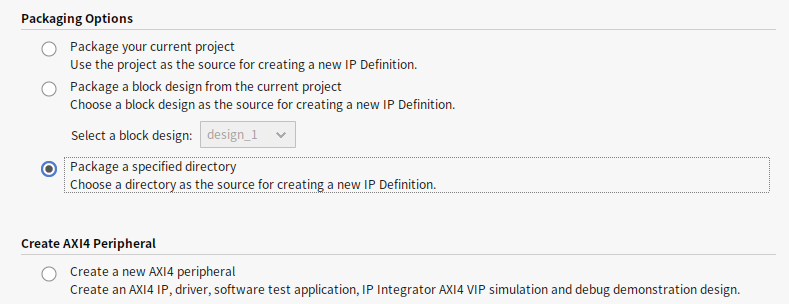
Since this is just a prototype, we use the simplest method by placing the above Verilog file in a separate folder (preferably in the same folder as the project). In this step, select the Package a specified directory option and choose that folder.
After clicking through, a new temporary Vivado project will open. The first important task is to check all our IO ports. When connecting IP in the block diagram, Vivado naturally won't know which Verilog IO Port is the AHB address or data. The Ports and Interfaces tab in the IP packaging tells Vivado which IO ports of this module correspond to which signals of AHB. The mapped signals will collapse and display with >, similar to the Clock and Reset Signals as shown in the picture.
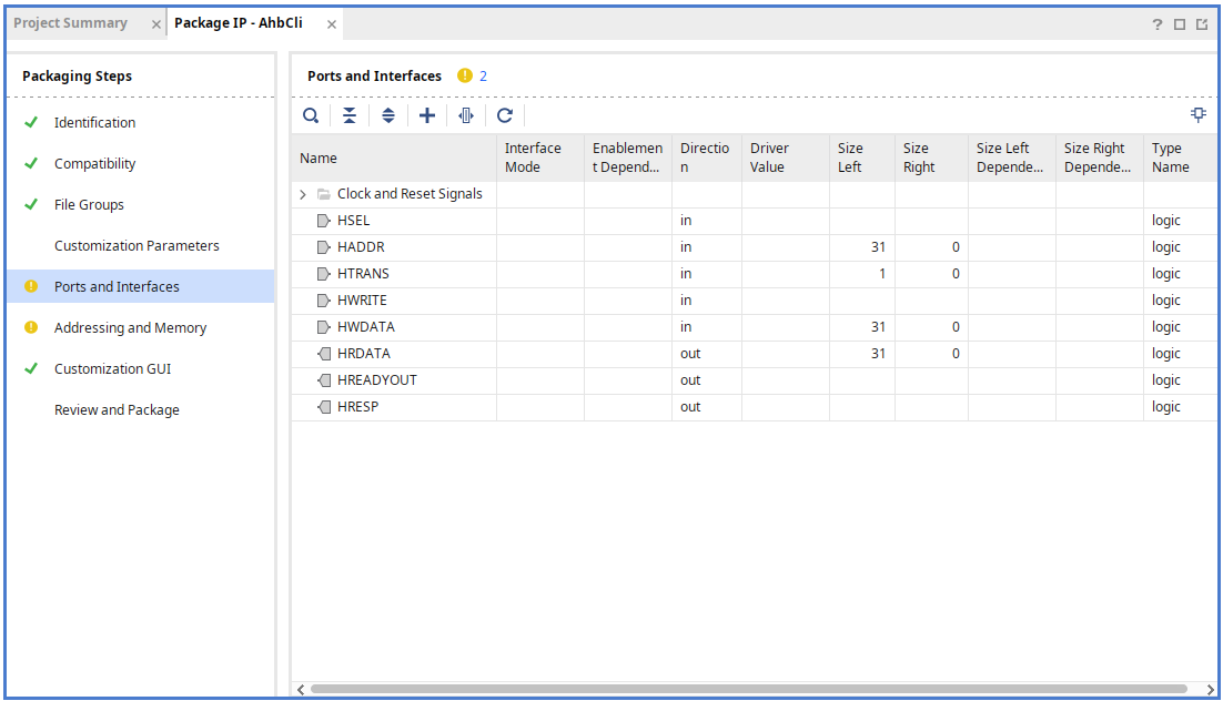
We need to map those signals starting with H to AHB by clicking the plus sign on the page (or right-clicking Add Bus Interface).
In the General tab:
- Select
Advanced/ahblite_rtlforInterface Definition - Use your favorite name for
Name - Set
Modeto slave
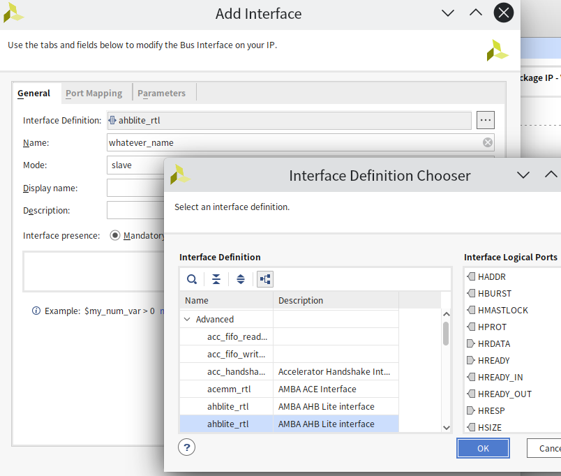
In Vivado, ahblite_rtl has two options; the second one adds HREADY_IN, HREADY_OUT; this is for multiple AHB Slaves to communicate with each other. To connect normally in the block diagram, select the second option here.
Next, we move to the Port Mapping page to map each port. Click once on the ports you want to map on the left and right, then press Map Ports.
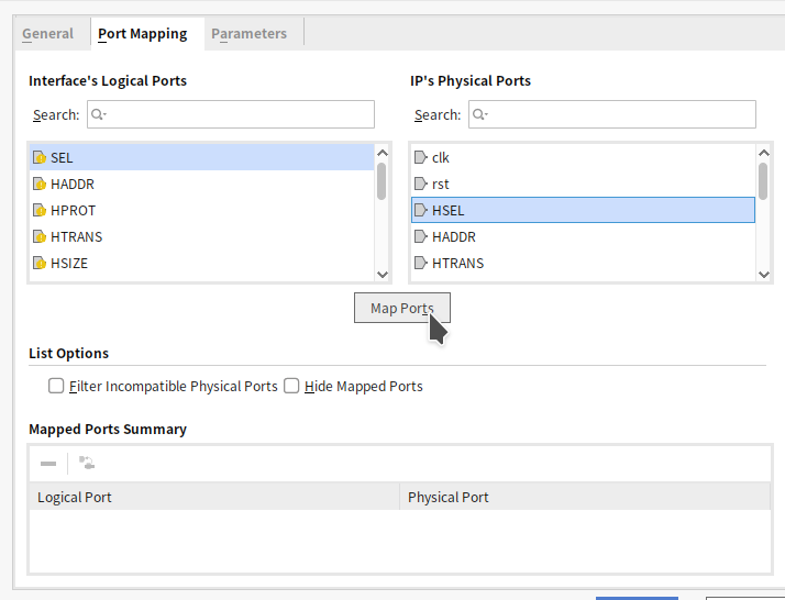
Since the Verilog code is almost named according to the AHB specification, mapping all the identical names is correct. However, there are two small points to pay attention to:
- In most AHB standard documents,
HREADY_INHREADY_OUTare calledHREADYHREADYOUT, slightly different names. HPROT,HMASTLOCK,HBURSTare not mapped, these are generally rare in simple AHB slaves and are optional signals.
After completing this step, the Ports and Interfaces page should become very clean:

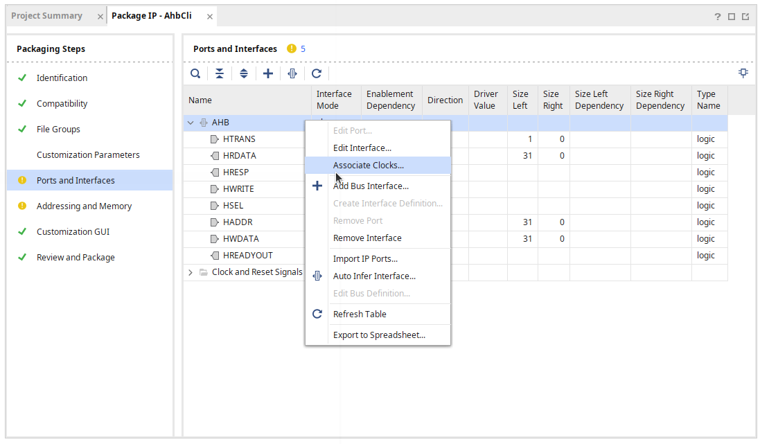
Sometimes the clock and reset signals are not automatically recognized. In such cases, we must manually add
clock_rtlandreset_rtlslaves and map the ports similarly.
Finally, right-click Associate Clocks on the AHB slave and reset to tell Vivado these signals are aligned with this clock signal.
Specifying the Address of the AHB Slave
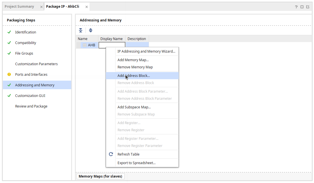
In the final step of creating AHB IP, we need to set the address of the AHB Slave, informing the SoC of this slave's address space size. For this, switch to the Addressing and Mapping tab. Initially a blank page will show
Run the Addressing and Memory Mapping Wizard to add a Memory Map or Address Space to Your IP, just click next until the end, selecting AHB slave in the process.
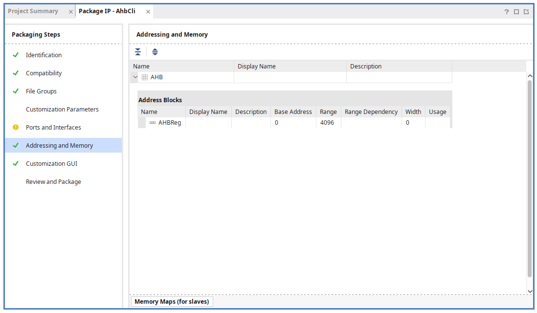
After completion, we should have an entry under this tab, right-click it and Add Address Block.
By default, a 4KB space is automatically assigned as shown below, which is sufficient for most simple IP control interfaces (for this IP, it is completely useless since we do not care about the Address). Let's click Review and Package, then yes until the IP packaging is completed.
Connecting to SoC
Next, we return to the SoC page to pull out the following three blocks and connect them together. Since we have already discussed how to do these things in AXILite , here we simply list the tasks to be done.
- Open a master port on the CPU, for example,
M_AXI_GP0. - Add
AXI AHBLite Bridgeand our new AHB IP. - Use AXI Interconnect to connect these three items, the path is
- CPU M_AXI_GP0 - AXI Interconnect Slave S00_AXI
- AXI Interconnect Master M00_AXI - AXI AHBLite Bridge AXI4
- AXI AHBLite Bridge M_AHB - AHB IP AHB
- Use the automatic connection function to connect all clocks and resets.
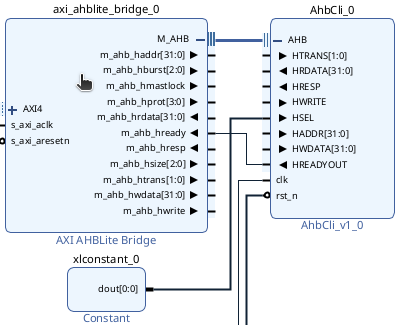
Finally, there is a smaller detail that needs to be handled manually.
As the AHB master provided by Vivado does not have a bus arbiter, it will not automatically connect the slave's HSEL and master ready. Vivado's check will report ports not connected at this moment.
Fortunately, when master and slave are one-to-one, we can use a Constant Block to set the slave HSEL to 1'b1, and connect
slave's HREAYOUT to master's HREADY, as shown below:
The complete connection wiring is as shown below:
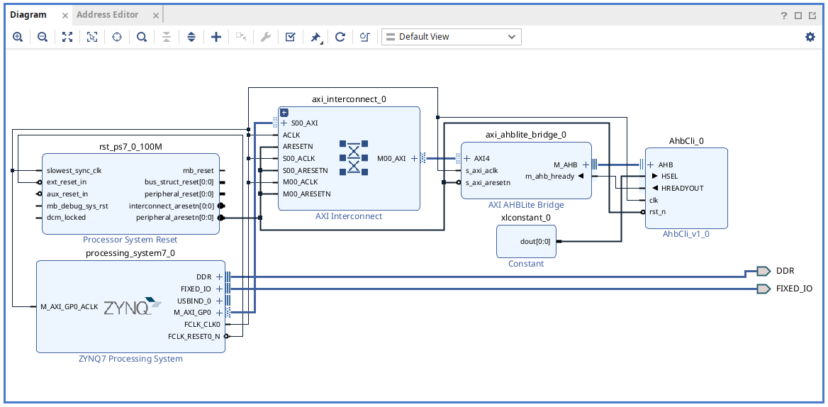
The last step is to open the Address Editor, assign a 4K memory block on the AHB port and note down the address assigned, which is an important number.
Testing Bitstream
Python Pynq
Unlike AXI lite, if AHB bus is connected, Python pynq cannot be used to load the .bitstream file and will encounter the following error:
Expected design_1:AhbCli_0[block]:AHB[port] to be SubordinatePort when assigning base address
The main reason is that Python pynq does not support non-AXI ports when parsing .hwh files, hence both AHB and APB cannot be used. From the available information, Xilinx has no plans to fix this issue, and using Pynq requires manual modification of the hwh metadata parser in the system, as suggested in the APB discussion.
C Pynq
Since Python Pynq is unsupported, we switch to using C API written by others and use mmap to access the AHB bus interval:
Below is the main.c used for testing, BASE_ADDR should be filled with the address given by Vivado in the Address Editor, compile it along with the C API's pynq_api.c into an executable:
#include <stdio.h>
#include <stdlib.h>
#include <fcntl.h>
#include <unistd.h>
#include <sys/mman.h>
#include <stdint.h>
#include "pynq_api.h"
#define BASE_ADDR 0x43C00000
#define AHB_BASE_ADDR 0x43C10000
#define MEM_SIZE 0x1000 // 4 KB
int main(int argc, char *argv[]) {
if (argc != 2) {
fprintf(stderr, "Usage: *.bit\n");
return 1;
}
char *bitstream_path = argv[1];
printf("Creating overlay device from:\n");
printf(" Bitstream: %s\n", bitstream_path);
if (PYNQ_loadBitstream(bitstream_path) == PYNQ_ERROR) {
fprintf(stderr, "Failed to load bitstream\n");
return 1;
}
printf(" Bitstream loaded successfully\n");
int fd;
volatile uint32_t *map_base;
// Open /dev/mem
fd = open("/dev/mem", O_RDWR | O_SYNC);
if (fd < 0) {
perror("open");
return 1;
}
// Map physical address to user space
map_base = mmap(NULL, MEM_SIZE, PROT_READ | PROT_WRITE,
MAP_SHARED, fd, BASE_ADDR);
if (map_base == MAP_FAILED) {
perror("mmap");
close(fd);
return 1;
}
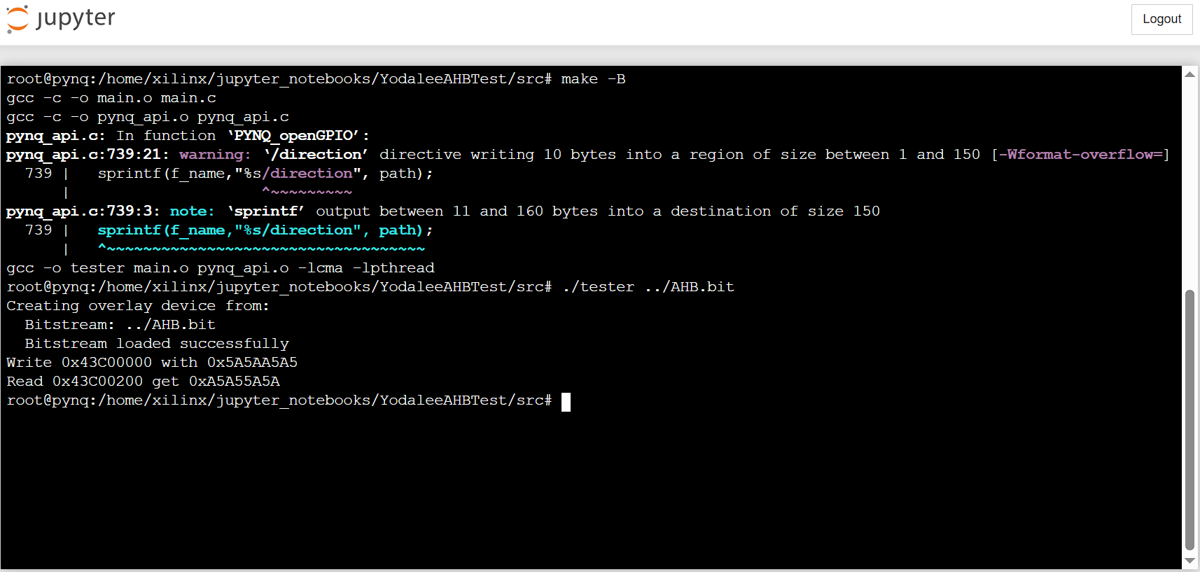
printf("Write 0x%08X with 0x%08X\n", BASE_ADDR, map_base[0] = 0x5a5aa5a5);
printf("Read 0x%08X get 0x%08X\n", BASE_ADDR + 512, map_base[0]);
// Unmap and close
munmap((void *)map_base, MEM_SIZE);
close(fd);
return 0;
}
The compile and execution result is as follows:
Conclusion
This article explains how to connect on the IP interface with a common AHB bus. Of course, Vivado also provides various different buses as there are many options in Interface Definition. This article serves as a foundation; in the next part, we will do similar things when connecting AXI Stream.