This content is translated with AI. Please refer to the original Traditional Chinese version (zh-TW) for accuracy.
In the previous article, we saw how to connect the AHB bus. In this article, let's take a look at AXI stream. If you have seen the usage of the AXI Lite interface, it helps convert AXI reading and writing into internal registers. However, each read and write is a time-consuming process. When there is a large amount of data that needs reading and writing, using AXI Lite and opening up hundreds of registers in the read and write space is very inefficient, making it difficult to efficiently send data to or from the IP.
AXI Stream Interface
The AXI stream is designed for this purpose. On the AXI stream interface, only the following ports are left:
- valid
- ready
- data
- last
- (optional) strobe
- (optional) keep
Every valid/ready handshake transmits data, a last assert indicates that this handshake is the last piece of data, and strobe and keep are used to indicate the validity of individual bits in the data. On a 32-bit AXI stream bus, the strobe and keep ports are both 4 bits; for a 64-bit bus, they are 8 bits.
Here's a simple summary of AXI stream strobe and keep pairing:
| Strobe = 1 | Keep = 1 | Data |
| Strobe = 1 | Keep = 0 | Don't use |
| Strobe = 0 | Keep = 1 | Position |
| Strobe = 0 | Keep = 0 | Null |
The so-called Position bytes refer to inserting some check codes, such as Hamming code, in the transmission of pictures or large data, or indicating the current position in the entire batch of data being transmitted, such as marking the beginning of transmission as 00, and so on. For related reference materials, you can first see the reference Quick Start Guide on AXI4 Bus — AXI4-Stream or directly read ARM's specification document AMBA 4 AXI4-Stream Protocol Specification .
By cooperating with the DMA module on the PS side, memory read and write can be performed at full speed. In this article, we will see how to implement a module that receives AXI stream, flooding large amounts of data from memory to the module. The main reference for this article (virtually a translation) comes from the following two articles:
Creating IP
Test Module
In this round, we first implement a unidirectional module with only stream write-in. To make keep useful, the implemented module specifications are as follows:
The input data will have each byte reversed, then each byte will be summed, and the result will be output.
Again, we ask AI for implementation (this time the prompt was difficult to give, and in the end, AI used a lot of functions and didn't handle axi keep, so I made minor fixes):
Input 32 bits AXI stream
Output 8 bits o_data
The module should flip each valid byte transferred, and sum the result to o_data
Keep the output until next DMA transfer
Save it as StreamAdder.sv
Packaging IP
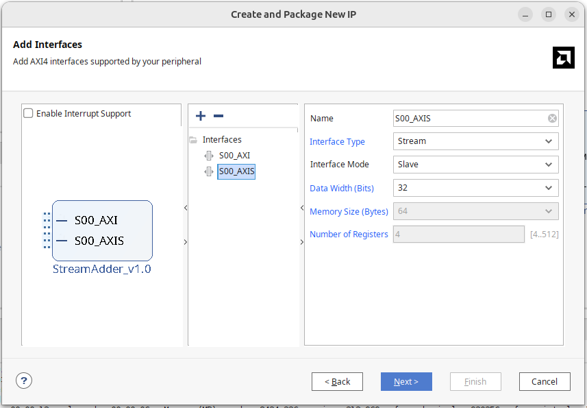
In Vivado, create a new IP:
- Tools -> Create and Package New IP
- Choose to Create a new AXI4 Peripheral and name the module StreamAdder
- Add an AXI stream interface in the AXI interface
- Set the interface as Slave
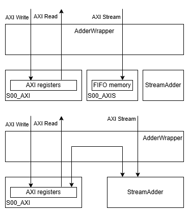
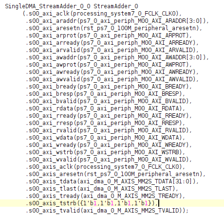
In the newly created module, you will see a module named S00_AXIS. Vivado would generate a module to capture AXI Lite signals for reading and writing its internal registers for AXI Lite. Similarly, the AXIS module can capture AXI Slave stream signals and write them to its FIFO memory. Of course, we could add logic to read data out from the FIFO memory within the AXIS module, but our module can already receive AXI stream, so we deleted the StreamAdder_v1_0_S00_AXIS code and instance.
The default module connection is shown as in the above diagram. We will change it to the lower diagram:
The interface brought by AXI stream includes:
- s00_axis_tvalid
- s00_axis_tready
- s00_axis_tdata
- s00_axis_tlast
- s00_axis_tstrb
Connect the lines into our module.
If you do not want to use Vivado to automatically generate it, you can package the IP manually like in the previous AHB, choosing axis.
Block Diagram
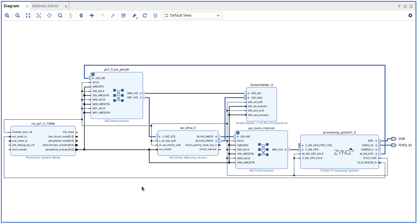
As before, establish a Pynq-Z2 project, configuring the Pynq7000 processor and our IP in the block diagram. The DMA is controlled using the AXI Direct Memory Access IP block, which can be renamed as dma, just like AXI Lite, Python would use this name to control the DMA module.
DMA Module Interface
Let's dissect the DMA module and see its interface:
S_AXI_LITE
AXI Slave control port used for configuring DMA, start/stop DMA, read state. Usually, after being wrapped in the python module abstracted by pynq, it won't be directly touched.
AXI Stream
DMA has two Stream ports:
- M_AXIS_MM2S where M indicates Master, i.e., initiating writing memory data into the AXI stream module
- S_AXIS_S2MM receives data from the stream module
Stream ports communicating with the IP can be blocked. If your IP input does not pull i_ready or output does not pull o_valid, it might deadlock the DMA module.
AXI Master
DMA has two AXI Master ports, connecting to Zynq's HP (High-Performance) AXI Slave ports to access memory, both are implementations of AXI full:
- M_AXI_MM2S, reading from (PS DRAM) and sending to AXI-Stream module.
- M_AXI_S2MM, receiving data from the AXI-Stream module and writing back to memory.
- M_AXI_SG, SG stands for Scatter Gather, allowing access to memory from multiple non-continuous locations.
In the PYNQ image, these HP ports are usually preset to 64-bit width, where MM stands for Memory-Mapped. The python driver on the end does not support scatter gather, only supporting DMA transfers from continuous memory; if scatter gather is needed, the M_AXI_SG port must be used, which we will omit for now, and cover when switching to advanced C programming driver.
Setting DMA Parameters
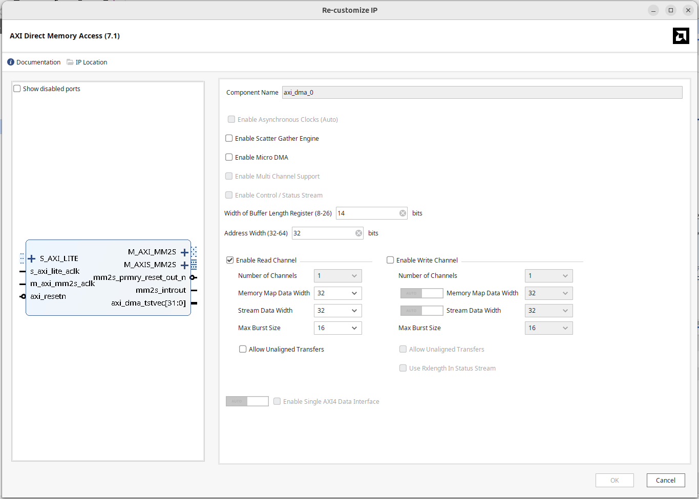
In Vivado, double-click to open DMA settings:
- Uncheck "Enable Scatter Gather Engine".
- Set the Buffer Length Register width according to the usage, setting it to a maximum of 26 bits, allowing a single transfer of 64 MB data. This field default value is only 14 bits, i.e., 16 KB of data, if your transmission buffer size exceeds the limit, the internal received data will be truncated; an oversized size can be solved by initiating multiple DMA transfers.
- Set Address Width to 32 bits. If using Zynq UltraScale+ and memory address width is larger, set it to 64 bits.
- Since we are reading data into the IP from memory, only check the Read channel, when unchecked, write-related channels: M_AXI_S2MM, S_AXIS_S2MM will disappear.
Memory-mapped data width and stream data width should both use 32 bits, although the 32 bits do not align with the width of the Zynq7000 HP port, that's okay, even if the widths were matched the DMA's M_AXI channel and the processor's HP channel below cannot connect directly, an AXI Interconnect needs to be inserted between them to mediate signal interfaces.
Connecting DMA Main Memory Port
For the DMA's Master port to access DRAM:
Inside Zynq, the four HP Ports are actually connected to PS Memory through two sets of memory switches:
- HP0 and HP1 share the same switch
- HP2 and HP3 share another switch
If the design requires only using two HP Ports, usually, it is recommended to choose a "not sharing a switch" combination for better performance, for example, HP0 with HP2 will be more efficient than HP0 with HP1.
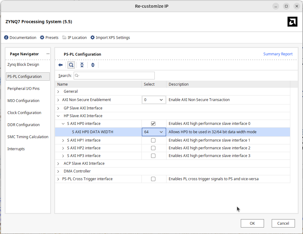
Zynq processors by default do not enable high-performance ports. In the processor settings:
- In PS/PL Configuration, HP Slave AXI Interface, enable S AXI HP0 / S AXI HP2.
- Set the HP port width to 64 bits.
The 64 bits width is set up when Pynq boots, and the Pynq default image is set to 64 bits, so this needs to be set to 64 only. If accidentally set to 32-bit, practically half of the data will be correctly transmitted, describing the symptom when doing DMA transfer, 32 bits of data are lost in every 64 bits of data transferred.
With the appearance of S_AXI_HP0 and then through the AXI interconnect, connect the M_AXI_MM2S of the DMA module to S_AXI_HP0. Lastly, connect the M_AXIS_MM2S of the DMA to the S_AXIS on our IP.
Completing the Design
The completed block diagram is shown below:
Press F6 for design validation to ensure there are no errors. Generate HDL wrapper and bitstream. Place the generated .bit and .hwh into a folder on the PYNQ board.
Pynq Test Program
In Python:
from pynq import Overlay, allocate
ol = Overlay("ReadDMA.bit")
After loading the Overlay, you can view the internal data with ?:
ol?

IP Blocks
----------
axi_dma_0 : pynq.lib.dma.DMA
StreamAdder_0 : pynq.overlay.DefaultIP
processing_system7_0 : pynq.overlay.DefaultIP
As shown above, it shows the DMA controller axi_dma_0 and StreamAdder_0 on AXI Lite. The DMA controller's sendchannel can be used to write data to the IP, and recvchannel for reading data, the latter isn't needed yet.
Assign to objects:
dma = ol.axi_dma_0
ip = ol.StreamAdder_0
dma_send = dma.sendchannel
Read DMA
To perform DMA read, first allocate a piece of memory for the DMA. Pynq provides an allocate function, in conjunction with numpy data types for memory allocation, here simply allocate 64 bits; use transfer to deliver data to the IP through the DMA module.
input_buffer = allocate(shape=(2,), dtype=np.uint32)
input_buffer[0] = 0x00000000
input_buffer[1] = 0x00000000
dma_send.transfer(input_buffer)
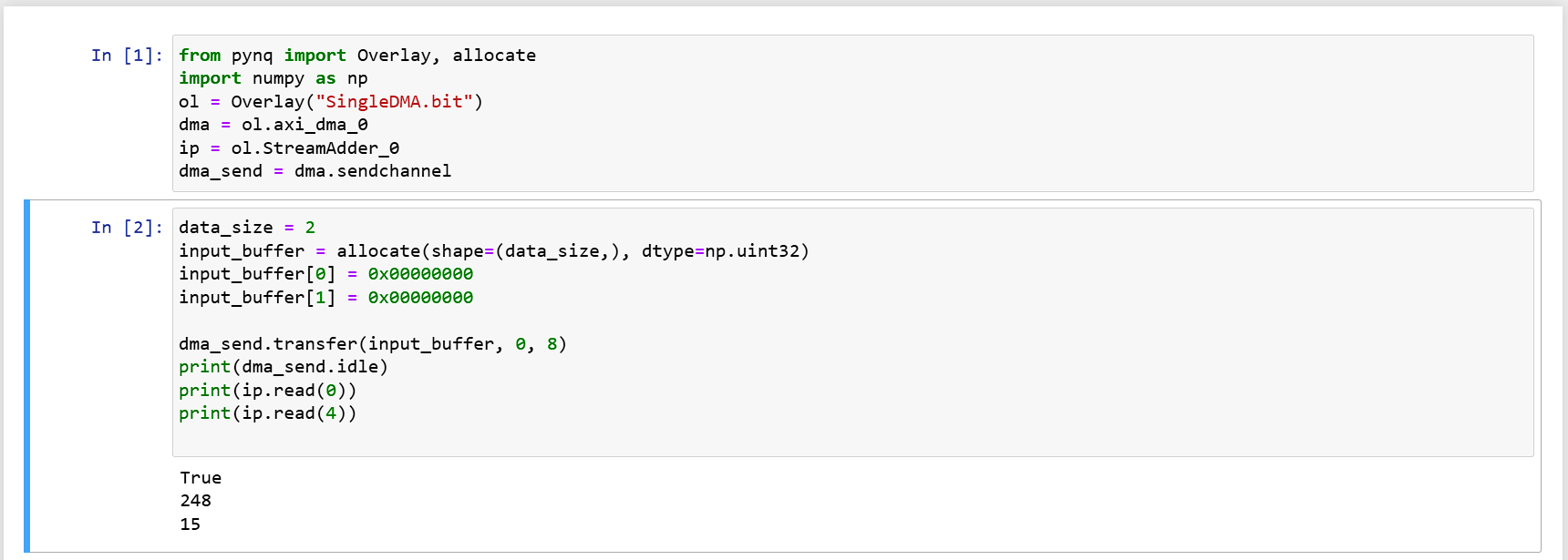
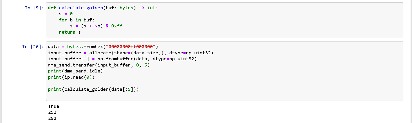
Will get 248 = -8 as the result
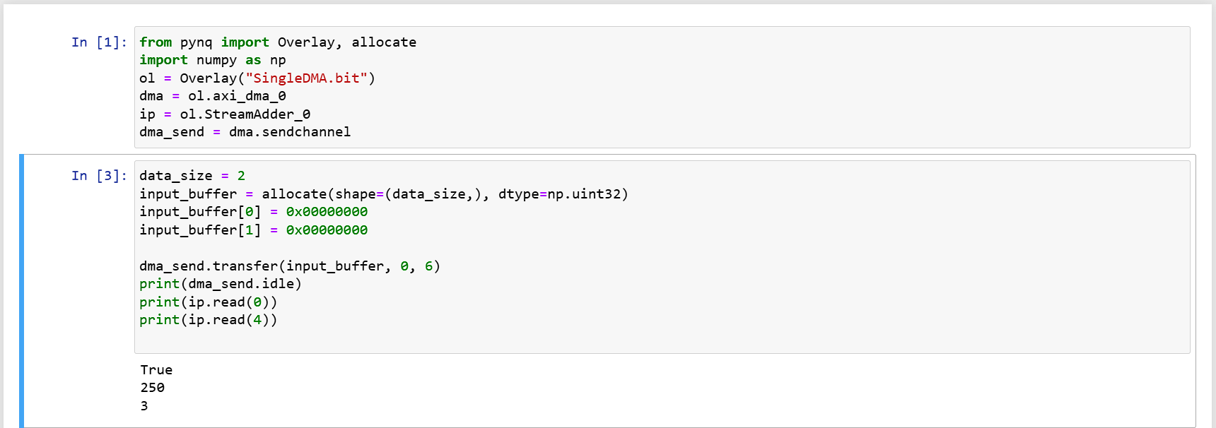
Because the example only has transfer, later I found the source code of pynq dma, and discovered its parameters, with the following implementation you can specify to only transfer 6 bytes inside, the preceding 1010 was not eaten by the hardware, so the output is 250 = -6.
input_buffer = allocate(shape=(2,), dtype=np.uint32)
input_buffer[0] = 0x00000000
input_buffer[1] = 0x10100000
dma_send.transfer(input_buffer, start=0, length=6)
print(ip.read(0))
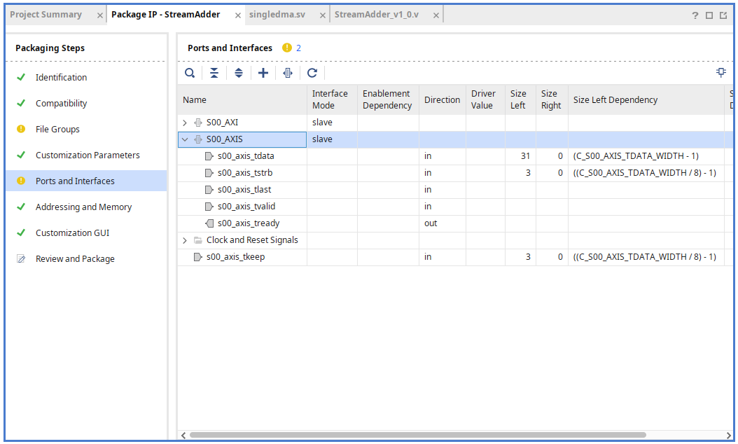
The Problem with Keep
If you have followed the steps above, you will find that the results of the second example are incorrect. The reason lies in the AXI stream keep wiring. The default AXI Stream interface has no KEEP port, so vivado does not connect the DMA module's keep line to our module, but even if you expand the AXI Stream you cannot see this, Vivado won't show individual port connection status, which I find very annoying... If I opened it, show the connection status.
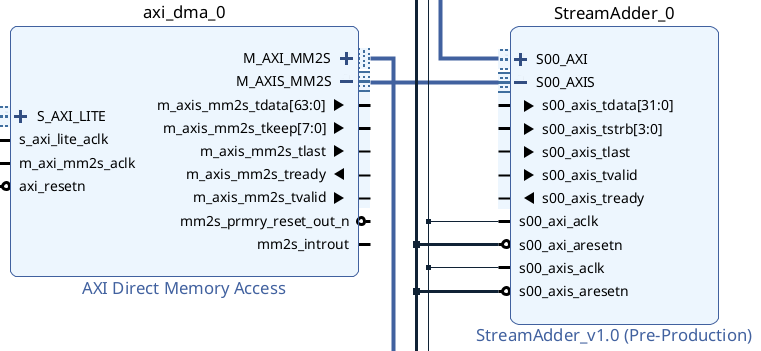
When generating code, Vivado will cleverly auto-connect 4 bits of 1, hence all bytes are eaten. This issue is very obscure, I once used ila core with debug lines in attempts, finding IP's side always receives all 1s for KEEP, opened up the generated top-level code to observe wiring and caught it.
To fix this problem, we need to return to IP, copying the tstrb port initially supplied, and renaming it to tkeep.
In Port and Interface, mapping the newly added tkeep to AXI Keep.
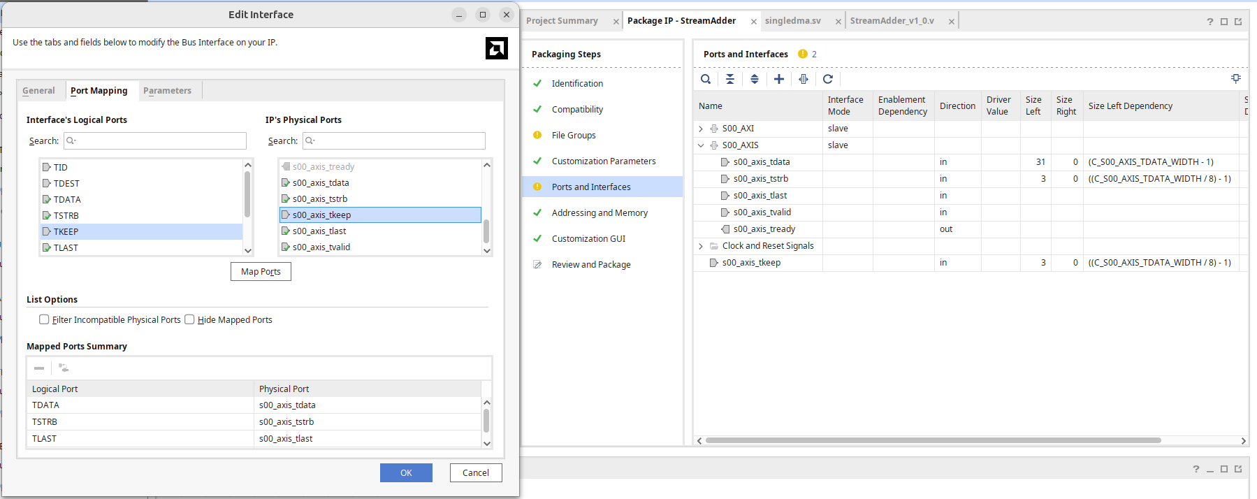
After repackaging like this, it's completed.
It's worth mentioning that the DMA driver of pynq will employ LSB placement (which makes sense as the memory address is low to high), during data sending keep value will be 1, 3, 7, F.
As to whether a DMA transfer with length 0 can be initiated, at least looking at the python driver source code will directly set the length to the input buffer's length, practically if the length is 0, simply do not initiate the DMA.
Efficient Approach
The aforementioned allocate returns an extended version of ndarray, allowing access to a physical address, rather than a pure numpy ndarray. When the driver needs to deliver a user-provided bytes object, and you don't want to keep calling the allocate function, refer to the discussion area implementation below:
# in constructor
buffer = allocate(shape=(BUF_SIZE,), dtype=np.uint32)

# in driver function
def send_data(data: bytes):
  buffer[:] = np.frombuffer(data, dtype=np.uint32)
  dma.transfer(buffer)
Conclusion
In this article, we demonstrated how to connect a DMA on a Xilinx FPGA and write a simple module to verify that DMA reading is indeed functioning. In the next article, we will see how to handle DMA writing.