This content is translated with AI. Please refer to the original Traditional Chinese version (zh-TW) for accuracy.
In the previous chapter , we looked at how to read data from memory and provide it to the IP module. This time we will do the opposite, sending data from the IP module to memory. A lot of things are similar to reading, so we will skip much of the DMA-related introduction, making it somewhat simpler.
Test Module
We will implement a module that only streams data in one direction for writing. The implemented module is as follows:
Input a 32 bits seed, the desired output length (in bytes) of 26 bits, and a start signal; Use the seed to output an LSFR random number of the specified length.
Since LFSR has many different tap forms, after looking at this Table of Linear Feedback Shift Registers , we chose 32, 30, 26, 25 bits as taps.
Again, we ask AI to help us implement:
Help me write a StreamLfsr module, with taps 32, 30, 26, 25
Input is the 32 bits initial seed, 26 bits output byte length, and 1 bit start signal
Output 32bits AXI Stream, which should output designated length of bytes by keep.
Below is the AI's implementation, which is not bad this time:
Create IP
First, package our IP:
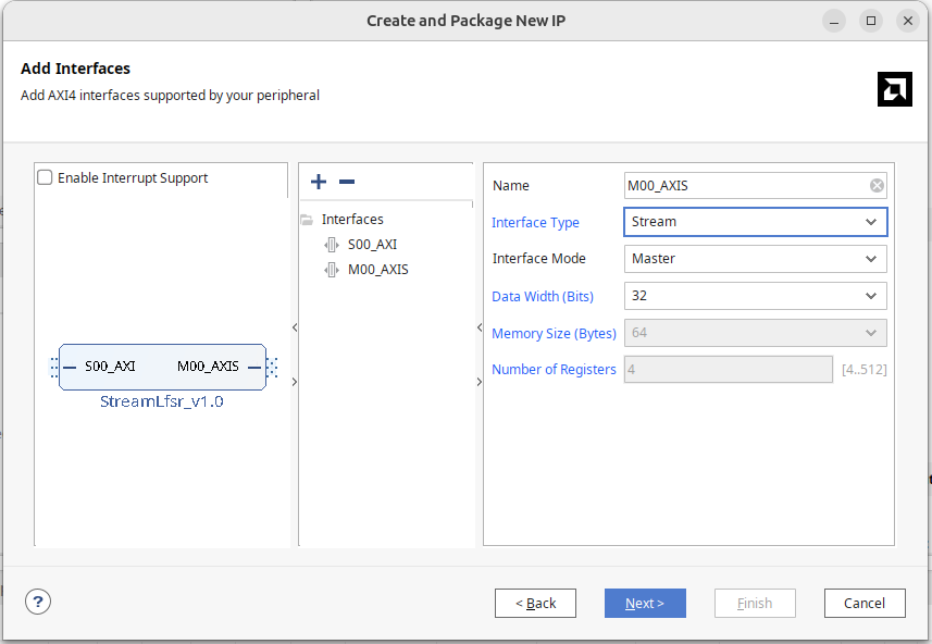
- Tools -> Create and Package New IP
- Choose Create a new AXI4 Peripheral, name the module StreamLfsr
- On the AXI interface, add an AXI stream interface, set it as Master
Like ReadDMA, you will see an M00_AXIS module with an internal FIFO memory that continuously cycles through:
- Wait for 32 cycles (the parameter can change how long to wait)
- Output the contents of the FIFO once completely
Since our module can output AXI stream, delete this StreamLfsr_v1_0_M00_AXIS.
Bring the AXI stream interface:
- m00_axis_tvalid
- m00_axis_tready
- m00_axis_tdata
- m00_axis_tlast
- m00_axis_tstrb
Connect it to our module. The generated master interface similarly does not have keep, so you can copy the tstrb port and change it to tkeep, mapping to the AXI stream keep in Port and Interface.
Alternatively, you can create the interface, choose axis, and set it as master.
Block Diagram
Add a Direct Memory Access Module to the Block Diagram.
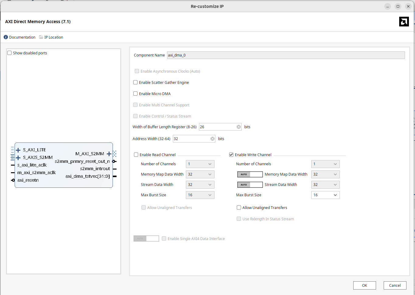
In Vivado, double-click to open DMA settings:
- Uncheck "Enable Scatter Gather Engine".
- Set the Buffer Length Register according to usage, configure the maximum width to 26 bits.
- Set Address Width to 32 bits.
- As we need to write the IP data into memory this time, only select the Write channel.
- Both Memory-mapped data width and stream data width use 32 bits.
Frankly, I don't understand why the DMA setting interfaces for Write and Read look different; that auto/manual toggle design is really baffling.
To make the DMA Master port access DRAM, open the S_AXI HP0 of the Zynq PS Block and set the HP port width to 64 bits.
The completed block diagram is as shown below:
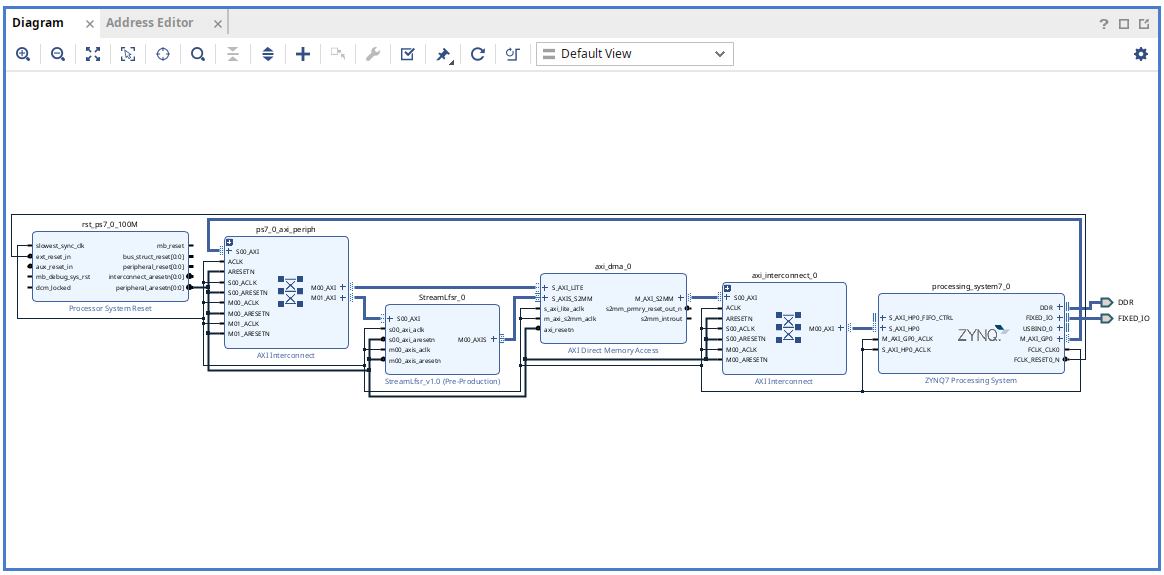
Press F6 to perform design verification, ensuring no errors.
Generate the HDL wrapper and bitstream.
Place the generated .bit and .hwh in the folder on the PYNQ board for the second part using DMA through Python.
On-board Testing
To verify the results, ask AI to write a python LFSR for verification:
Write me a python LFSR with seed input, tap ad 32, 30, 26, 25 function signature def lfsr(int seed, int byte_length) -> bytes
This is the AI-generated python implementation
Once the .bit file is loaded, use ? to see which modules can be called:
You will see the axi_dma_0 DMA controller and StreamLfsr_0 connected to the IP block on AXI Lite.
Following our design, we can implement a hw_lfsr function to allocate memory written by the IP module, write the seed, byte_length, start to activate hardware; use the DMA recvchannel to transfer and fill data into memory.
ip = ol.StreamLfsr_0
dma = ol.axi_dma_0
dma_recv = dma.recvchannel

def hw_lfsr(seed: int, byte_length: int) -> bytes:
    buffer = allocate(shape = (byte_length,), dtype = np.uint8)
    ip.write(0, seed)
    ip.write(4, byte_length)
    ip.write(8, 1)
    dma_recv.transfer(buffer)
    return buffer.tobytes()
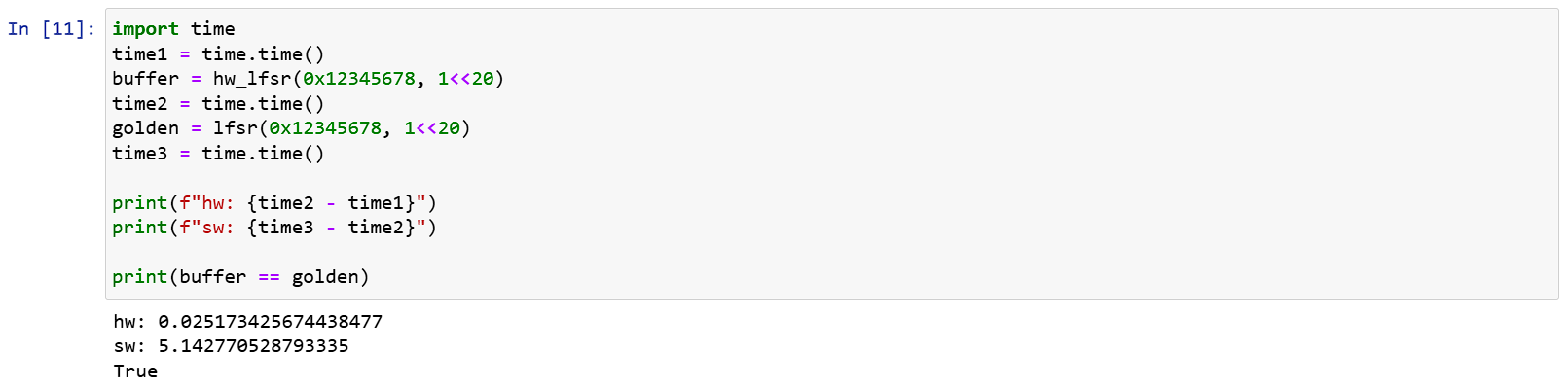
Execution results:
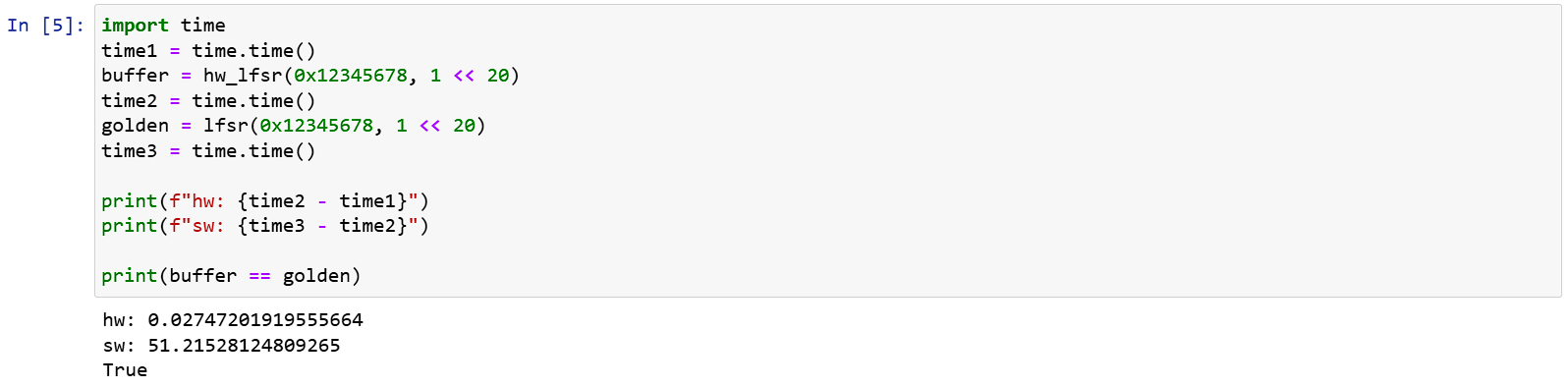
Software Acceleration
From above, you can see that although 1MB of data output from hardware and software has the same result, the software is really slow, taking 50s for just 1MB.
To accelerate it, output 16 bits each time by modifying as follows:
def lfsr(seed, n):
    if seed == 0:
        raise ValueError("Seed must be non-zero")
    state = seed & 0xffffffff
    output = bytearray()
    while len(output) < n:
        output += state.to_bytes(4, 'little')
        for i in range(2):
            feedback = (state >> 16 ^ state >> 14 ^
                        state >> 10 ^ state >> 9) & 0xffff
            state = ((state << 16) | feedback) & 0xffffffff
    return bytes(output[:n])
The execution results show considerable acceleration:
This demonstrates the speed difference between hardware (although Python here) and software. For hardware, as the Lsfr design is simple, the IP frequency can reach up to 100MHz. It can execute 1MB of random numbers in 2.6 ms and, combined with AXI Stream, can write directly into memory, running much faster than software.
The Problem with Last
In AXI Stream, Last is used to mark the end of the entire transmission. The hardware module processing the DMA is implemented according to the AXI stream specification, so it respects the result of this bit.
If we set the module to ignore settings and pull the last pin when 100 entries are output, then the driver can only pull 100 entries. If it tries to read 150 entries, as the 100th entry contains last, the following entries are ignored and filled with 0 by the driver.
Conversely, if the driver only requests 50 entries and no last signal appears, the driver gets stuck in waiting and can't initiate the next transfer. At this point, except for a direct reset, there's no way to recover.
Conclusion
In this article, we demonstrated how to connect DMA on Xilinx FPGA and write a simple module to verify that DMA writes actually work. By combining read and write AXI Streams, a module such as a FIFO with both read and write capabilities can be created.
I think that's enough about AXI. Next, let's look at Interrupts.